

Update
Also, VCN Transit Routing was updated with two major features last summer :
The 3rd use case exposed here (East/West traffic with “DRG Bouncing”) was not supported, and it is not possible anymore :
For East/West traffic with VTR, you must insert a compute instance and route to the Private IP, ideally a Network Security Appliance (you can find some in the marketplace).
– July 8th : transit routing through a Private IP
– July 16th : transit routing for Private access to Oracle Services Network
These recent updates enables two new use cases for VTR :
– North/South access consolidation with service insertion (routing to a security appliance),
– Private access to Oracle Services through Service Gateway from On-Premise.
In this article, I will present :
- the hub-and-spoke architecture concepts,
- the difference between Hub-and-Spokes and full-mesh,
- advantages and trade-offs with each,
- Some possible hub-and-spoke topologies with OCI,
- then the mechanics in OCI enabling these architectures.
In the next articles of this series, I will present the implementation details for each scenarios presented here.
What is a Hub-and-Spoke Networking Topology?
Literally, you can take the bicycle wheel image, with the Hub at the center and spokes connecting the nodes around the hub.
The Hub-and-Spoke model is a concept that can be applied to any network. Take for example the flight networks of a global air carrier: they are generally organized around major airports (hubs), with a constellation of regional airports connected to hubs and other regional airports. The main benefit is to reach more destination with less links.
In Computer Science, the “Hub-and-Spoke” architecture model (also known as “star network”) is used to connect several network nodes together, using a central point: the hub.

The Hub-and-Spoke model contrasts with full-mesh networks, which connects every nodes of the network together with a dedicated link.

Compared with a mesh model, the main characteristic of an Hub-and-Spoke model is the drastic reduction in the number of links required to interconnect every nodes of a network. This characteristic becomes crucial as node number increases.
To illustrate this, here is a table comparing the number of links required to interconnect all nodes of a network:
| # of Nodes | # of Links with Hub-and-Spoke | # of Links with Full-mesh |
| 3 | 2 | 3 |
| 4 | 3 | 6 |
| 5 | 4 | 10 |
| 6 | 5 | 15 |
| 7 | 6 | 21 |
| 8 | 7 | 28 |
A full-mesh network follows the formula below to determine the required links number:
L = N x (N – 1)/2
Where L is Links, and N is Nodes.
The links number scales exponentially as the network gets bigger.
The full-mesh model excels when latency is the key criteria, as every node have a direct connection to any node in the network without any intermediate.
In contrast, a Hub-and-Spoke network links number scales linearly as it grows: each new node requires only one new link. However, there is an initial cost of one additional node to plan for the hub. Here is the formula:
L = N – 1
Again, where L is Links, and N is Nodes.
Obviously, it is possible to mix and match the two interconnection models inside the same network architecture to get a bespoke solution.
You can imagine here a global air carrier connecting two major hubs together and handling the regional traffic through each hubs. Sometimes two network nodes are connected directly, without going down to the central hub.
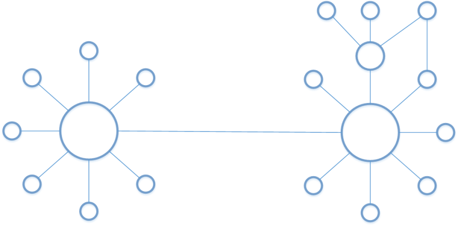
You can also transpose this diagram to several VCNs and OCI regions: interconnection concepts are exactly the same.
Why a Hub-and-Spoke Networking Topology in OCI?
It enables you to use a central VCN to offer connectivity for other VCNs inside the same cloud region. Without the VTR feature, a multi-VCN design would require that each VCN have his own connection to on-premises networks (n x VPN, n x FastConnect links, etc …).
1. Mutualize on-premises access
The first benefit is to mutualize access to on-premises networks for several VCN:
- the central VCN (HUB) handles the connections to on-premises networks through the DRG,
- other VCNs (SPOKE) establish a peering with the HUB VCN and gains access to connected networks behind the HUB VCN.
The “HUB” VCN is used by the “SPOKE” VCNs only as a transit to reach the destination: traffic is routed according to the defined rules.
Reducing the number of links to remote networks (IPSec VPN or dedicated links with FastConnect) allows to:
- reduce the administrative tasks and monitor less links,
- enhance the global security, as there will be less entry points to control,
- reduce costs when using dedicated links.
When the traffic comes from a “SPOKE” VCN to the “HUB” VCN, it can be redirected:
- directly to the HUB VCN’s DRG,
- to an instance IP located inside a subnet of the HUB VCN.
The 2nd option allows to deploy a 3rd party security appliance for example, and enforce any traffic crossing the HUB VCN.
2. Simplifying the multi-region/multi-VCN architectures
This scenario is somehow similar to the first one, with one difference: the remote networks are not on-premises but inside another OCI region. We connect here two star networks by a Remote Peering Connection (RPC).
We build up here on several OCI VCN features :
- Remote Peering Connection to interconnect two HUB VCNs in two OCI regions, using the OCI private backbone,
- VCN Transit Routing to share this RPC with other VCNs in each region.
3. Centralise and Reduce VCN to VCN connections inside a region
Before introduction of the VCN Transit Routing feature, it was already possible to build a point-to-point connection between two VCN using a Local Peering Gateway (LPG). When trying to connect several VCNs together, this solution would use the “mesh networks” connectivity model. And as we have seen it previously, as the network grows, it becomes more and more complex to operate and you may hit some limitations.
VTR is building-up on the LPG feature and allows to interconnect VCNs from a same region using a central VCN.
Another benefit of this network topology is to be able to better control East/West traffic inside a region, and possibly enforce traffic with a 3rd party security solution deployed as an instance inside the HUB VCN. Using VTR, you can also go beyond the default limit of 10 LPG per VCN.
How Hub-and-Spoke Networking Topologies are enabled in OCI?
In OCI, a start network is build around VCNs, LPGs, DRG and routing tables. The novelty here is that you can now also attach a Route Table to DRGs and LPGs, in addition to subnets: we have a broad range of tools allowing for modularity in networking architectures.
Using these two new Route Table attachment options, we can define which path each packet entering the Transit VCN should follow:
- Route Table on LPG can route traffic toward:
- the VCN’s DRG (to exit from the cloud region),
- an Instance IP, ideally located inside the Transit VCN.
- Route Table on DRG can route traffic toward:
- one of the LPGs on the Transit VCN in order to reach one of the SPOKE VCN,
- an Instance IP as with the previous case.
The diagram below illustrates how to configure each Route Table to enable East/West traffic between VCN2 & VCN3 and the traffic flow between two instances.
The networking constructs used to build our Virtual Cloud Network are logical (they are part of the SDN solution), and are decorrelated from the actual OCI physical network topology. Inserting LPGs into the virtual architecture have no impact on the latency and we are still at sub-milliseconds of latency inside a region.
Next articles in this series will take us to the implementation details of the 3 scenarios presented here:
- Mutualize on-premises access,
- Simplify multi-region/multi-VCN architectures,
- Centralize and reduce VCN-to-VCN connections inside a region.
They will include configuration synoptic and a Terraform template to create the presented topologies.
Contrary to this:
Route Table on LPG can route traffic toward:
the VCN’s DRG (to exit from the cloud region),
an Instance IP, ideally located inside the Transit VCN.
Route Table on DRG can route traffic toward:
one of the LPGs on the Transit VCN in order to reach one of the SPOKE VCN,
an Instance IP as with the previous case.
The DRG’s route table only accepts an LPG as nexthop and an LPGs route table will only take a DRG as next hop. I believe the private ip as nexthop is in the pipeline. It is there for subnet route tables though
Hi Nihal,
Thank you for your feedback.
You are correct for “Private IP Next Hop from DRG” : this feature was released in July 8th.
Thanks for the reply. I’ve tested it out and it works fine. https://docs.cloud.oracle.com/iaas/releasenotes/changes/332687e8-2cdd-4a33-b6a8-af9711d098b9/