Just don’t use the same RSA key over and over, between projects, tenants, users … In any form : api AuthN keys or ssh keys. Please. Just don’t.
That being said, security principals needs to be easy to implement, with minimal efforts. If not, unpleasant shortcuts will be taken at some point.
Ideally, you should always manage keys with a vault, either HSM backed or with a software secret management solution.
However, it is not always possible to have the infrastructure components to manage secrets. In this case, following these principles is the bare minimum:
1️⃣ Generate a new key for each purpose,
2️⃣ Do not repurpose 🙂,
3️⃣ Make the key as transient as possible,
4️⃣ Ideally, each key should be a disposable.
To implement these four principles, we need solve two problems:
easily generate new key pairs,
easily distribute/update public keys.
Generating rsa key pairs
Generating ssh key pairs is relatively easy with openssl.
The example below shows how to generate a private key in .pem format. It is just 3 commands to have a usable private and public key:
# generate rsa private key
openssl genrsa -out key.pem 2048
#adjust filesystem rights
chmod go-rwx key.pem
#extract public key for distribution
openssl rsa -pubout -in key.pem -out key_public.pem
You have now two files:
key.pem: your private key, which needs to be protected,
key_public.pem: the corresponding public key, which needs to be distributed on remote systems when access will be granted.
This is the format used for OCI API keys. More information can be found here.
For ssh usage, you need to use ssh-keygen to have your keys in the correct format for ssh. More information can be found here.
Distributing public keys
The goal is to upload the public key to an OCI user profile, in a programatic way. This requires to use one of the available sdk options (oci cli, terraform, etc …), so you will obviously need an initial account with access to API already configured.
We will automate the configuration of any subsequent accounts.
Using OCI CLI
Once you have generated your key pair, it take one command to update an OCI IAM User with this key: oci iam user api-key upload --user-id <your-user-ocid> --key-file <key_public.pem>
You will need to first generate a key pair with the generate_RSA-key.sh shell script, then apply the terraform configuration after you have configured the terraform.tfvars file with your information tenant information.
Terraform configurations are idempotent by default. The advantages over the oci cli method are the tear-down and how updates to key pairs are handled:
if a new key is generated, terraform will reflect the change,
you can easily suppress the api key when you are done with a terraform destroy.
Tagging is the act of putting labels on objects. There is 1:n relation, meaning one object can have many labels applied to it.
Traditional systems that implement tags are usually backed with a “set” data structure: an unordered/unindexed collection. The key is the value. E.g: Prod, Dev, CC127638, Finance
Immediate limitation: you have to guess the key from the value. For the previous example, it may be obvious that we are talking about environment or lane for the Prod and Dev values, depending on your company’s lingo. But how would you differentiate a cost center and an app owner? It is subject to interpretation.
We need a key:value structure for better clarity.
On modern cloud platforms, Tags tends to be at least a key:value pair which make use of “dictionary” data type. E.g: Environment:Prod, CostCenter:127638,Owner:Finance.
On OCI, this is the first type of tags available, and it is called Freeform Tags. You can use it with arbitrary keys:value pairs.
The second type of tags you can use on OCI is called Defined Tags. They add a namespace construct to Tags. The data type becomes key:dic, the value is a dictionary itself, hence able to contain a nested key:value pair.
This is particularly interesting to aggregate directly related tags together. E.g: Operations.Environment:Prod, Operations.Owner:Finance, Operations.State:Live, Finance.CostCenter:127368, Finance.Budget:378473
The syntax is now namespace.key:value
Another advantage of this new construct is the scheme definition: the keys are not arbitrary anymore, they are defined in advance. This effectively helps to prevent Tag Sprawl ans misspelling.
There is much more to Defined Tags on OCI, and we will explore it later. For now we can summarize the following about Tags & OCI:
Freeform Tags are arbitrary key:value pairs,
Defined Tags are a collection of tags regrouped as namespaces.
1️⃣ You should use Defined Tags almost every time, as they are more feature rich and allows better control and governance.
A good use case for Freeform Tags
Freeform Tags are best to use when you don’t have Defined Tags ready yet, just after tenant creation for example. They can also be useful when you want to keep some tags independent from the global tagging strategy and/or avoid any circular dependency. How do you tag your tagging namespaces with a defined tag during an automated process? 😅 -> 🐔 + 🥚
2️⃣ Make it clear whether a component is created manually or by an automated process.
For exemple, when deploying infrastructure with Terraform, you can « watermark » the resource with a specific freeform tag, same with other automation tools: Terraformed: <value> Ansibled: <value> Hashipacked: <value>
<value> may be a timestamp dated from the last modification time. This « watermarking » Freeform Tag would just be absent if the resource is created manually.
That’s it: you can now quickly search for the presence or absence of your watermarks.
An alternative proposition: using more generic tags to label your IaC strategy : Automation: Terraformed/Ansibled/xxx ConfigMgmt: Chef/Puppet/Salt/Tower
This second solution may be more suited for a defined tag namespace.
Additional metadata regarding the automation tool may be useful: for exemple, if the component is provisioned by a terraform module, it doesn’t hurts to add a Freeform Tag for that: TF_Module: xxx.
Using freeform tags for objects created by Terraform allows to tag any resource right from the beginning, without having to rely on Tag Namespaces not being provisioned yet.
3️⃣ When editing an existing object with Terraform, for example the Default Security List automatically created with a VCN, leave a trail for any other user : Terraformed: Default Security Rules edited.
Beside of the exposed use cases, try to keep Freeform Tags usage really exceptional and use Defined Tags instead as much as possible. They offers lot more of features like usage control, consistency, defaults, variables, and more to come.
New features and innovation for Tags comes only on Defined Tags, not on Freeform Tags.
On the Resources Naming Conventions in Enterprise IT
When (1)Naming, (2)Filing and (3)labeling are done right for your resources, we can assume that you have a well defined environment. The problem is to agree upon what “done right” is.
For (2)Filing and (3)labeling, your platform will generally propose you some tools to help. You still have to decide how you use them, but the feature’s design will probably suggest some pattern.
In OCI, there is Compartments & Tags👌and we will discuss about some ideas to make the best use of them later.
But for (1)naming, that’s up to you to decide about your strategy: cryptic IT naming convention can ruin all the benefits of a careful filling and labeling strategy ❌
Let’s talk about our naming practices in IT.
At some point in his career, any ops people have named the servers after planets ☄️, greek gods 🔱⚡️or superheroes 🦸♀️ 🦸♂️ names, sometimes a mix of all of the above. I am guilty of still administrating the town of Springfield and the Simpsons characters in my home network. 😅
And I am sure there is more than one system administrator that named all the servers after the Game of Thrones characters names.
It may be fun and cristal clear for you and your core ops squad, but you eventually acknowledge that a marvel theme for your servers was not the best idea, when the new team member reboot Hulk in the middle of the day genuinely thinking that this server was just a random lab experimentation👌. That’s correct in some ways, Hulk is just an experimentation that gone out of control. But this non-sense ends up written in a post mortem report, eventually read by the boss of your boss. 🤦🏻♂️
Explaining this post mortem to a pointy haired boss have the potential for a great Dilbert strip 😂
The opposite behavior is to overreact with too much codification. That’s how you end up with server names like this: OSGTNA1S2, VFRI23OPR003
Still nobody have a clue at first sight about what these resources are and what they do, unless you already practice these names for some time. At best there is little difference from the planet names, and you probably go back and forth to the CMDB (if you happen to have one up-to-date).
🎁 Bonus: you wasted 10 man-days to produce the initial naming convention proposal, endured a fair number of meetings and email chains to have everybody agreed upon it. Yet, every new service addition represent a major challenge to find the trigram that will fit with the whole. 🤦♀️
🙅🏻♂️ Enough. You probably don’t need a naming convention that takes 4 hours to read, 4 weeks to master and generates names that can be used as an RSA private key. Not for naming cloud logical objects at least.
This actual “art” of naming conventions is a legacy of constraints that are mainly not relevant anymore, certainly not when working with cloud logical object :
there was no easy way to attach metadata directly on a resource, so we tried to codify it in the name,
restriction on allowed character type and number, prevented plain words usage.
Your resource name is not your metadata store anymore, you have tags for that.
Why not calling your first desk, just “desk1”? 🤔— That’s much more descriptive. If you need more context about this desk, just put some tags on it. That’s where you want your metadata, not embedded on the name of the resource: “Desk1: grey, room 5, bought in 2020, used by John Doe” 🆚 DESK1WH20R5JDO.
Usual pushbacks are all variations from the following three:
« I do some magic filtering on the name and perform operations using grep, awk, cut & sed »
«I need that precise codification to speed my troubleshooting process.»
« I want to know everything about the resource just by reading its name »
Let’s be pragmatic and adopt a middle ground position between OVNDE13PR1 and VCN1.
It is ok to have some descriptive elements in the name of a resource, but there is no need to over-codify everything in it: you will actually loose in clarity.
Modern CMP (cloud management platforms) do not rely on resources name: a universal unique identifier is used for references (uuid), and the display name becomes just another metadata element.
With current cloud technologies, the display name property often don’t have to be unique across the entire platform and have room for long naming. 50 chars is pretty common, with some solution allowing up to 255 chars.
Here is some principles for a clear and obvious naming convention, to eventually solve (1)naming:
1️⃣ Define clearly the lingo related to your technology stack, the acronyms you use for objects, features and concepts, 2️⃣ Simply name the resource after its purpose, in plain word, 3️⃣ Add naming-segments in the resource name for information related to the resource purpose, with terms from your lingo 4️⃣ When possible, enforce the resource context with a filing structure that represent your organisation’s structure. 5️⃣ Put any other information in Tags!
Update The 3rd use case exposed here (East/West traffic with “DRG Bouncing”) was not supported, and it is not possible anymore : For East/West traffic with VTR, you must insert a compute instance and route to the Private IP, ideally a Network Security Appliance (you can find some in the marketplace).
These recent updates enables two new use cases for VTR : – North/South access consolidation with service insertion (routing to a security appliance), – Private access to Oracle Services through Service Gateway from On-Premise.
In this article, I will present :
the hub-and-spoke architecture concepts,
the difference between Hub-and-Spokes and full-mesh,
advantages and trade-offs with each,
Some possible hub-and-spoke topologies with OCI,
then the mechanics in OCI enabling these architectures.
In the next articles of this series, I will present the implementation details for each scenarios presented here.
What is a Hub-and-Spoke Networking Topology?
Literally, you can take the bicycle wheel image, with the Hub at the center and spokes connecting the nodes around the hub.
The
Hub-and-Spoke model is a concept that can be applied to any network.
Take for example the flight networks of a global air carrier: they are
generally organized around major airports (hubs), with a constellation
of regional airports connected to hubs and other regional airports. The main benefit is to reach more destination with less links.
In
Computer Science, the “Hub-and-Spoke” architecture model (also known as
“star network”) is used to connect several network nodes together,
using a central point: the hub.
The
Hub-and-Spoke model contrasts with full-mesh networks, which connects
every nodes of the network together with a dedicated link.
Compared
with a mesh model, the main characteristic of an Hub-and-Spoke model is
the drastic reduction in the number of links required to interconnect
every nodes of a network. This characteristic becomes crucial as node
number increases.
To illustrate this, here is a table comparing the number of links required to interconnect all nodes of a network:
# of Nodes
# of Links with Hub-and-Spoke
# of Links with Full-mesh
3
2
3
4
3
6
5
4
10
6
5
15
7
6
21
8
7
28
A full-mesh network follows the formula below to determine the required links number:
L = N x (N – 1)/2
Where L is Links, and N is Nodes.
The links number scales exponentially as the network gets bigger.
The full-mesh model excels when latency is the key criteria, as every node have a direct connection to any node in the network without any intermediate.
In
contrast, a Hub-and-Spoke network links number scales linearly as it
grows: each new node requires only one new link. However, there is an
initial cost of one additional node to plan for the hub. Here is the
formula:
L = N – 1
Again, where L is Links, and N is Nodes.
Obviously,
it is possible to mix and match the two interconnection models inside
the same network architecture to get a bespoke solution.
You
can imagine here a global air carrier connecting two major hubs
together and handling the regional traffic through each hubs. Sometimes
two network nodes are connected directly, without going down to the
central hub.
You can also transpose this diagram to several VCNs and OCI regions: interconnection concepts are exactly the same.
Why a Hub-and-Spoke Networking Topology in OCI?
It
enables you to use a central VCN to offer connectivity for other VCNs
inside the same cloud region. Without the VTR feature, a multi-VCN
design would require that each VCN have his own connection to
on-premises networks (n x VPN, n x FastConnect links, etc …).
1. Mutualize on-premises access
The first benefit is to mutualize access to on-premises networks for several VCN:
the central VCN (HUB) handles the connections to on-premises networks through the DRG,
other VCNs (SPOKE) establish a peering with the HUB VCN and gains access to connected networks behind the HUB VCN.
The
“HUB” VCN is used by the “SPOKE” VCNs only as a transit to reach the
destination: traffic is routed according to the defined rules.
Reducing the number of links to remote networks (IPSec VPN or dedicated links with FastConnect) allows to:
reduce the administrative tasks and monitor less links,
enhance the global security, as there will be less entry points to control,
reduce costs when using dedicated links.
When the traffic comes from a “SPOKE” VCN to the “HUB” VCN, it can be redirected:
directly to the HUB VCN’s DRG,
to an instance IP located inside a subnet of the HUB VCN.
The 2nd option allows to deploy a 3rd party security appliance for example, and enforce any traffic crossing the HUB VCN.
2. Simplifying the multi-region/multi-VCN architectures
This
scenario is somehow similar to the first one, with one difference: the
remote networks are not on-premises but inside another OCI region. We
connect here two star networks by a Remote Peering Connection (RPC).
We build up here on several OCI VCN features :
Remote Peering Connection to interconnect two HUB VCNs in two OCI regions, using the OCI private backbone,
VCN Transit Routing to share this RPC with other VCNs in each region.
3. Centralise and Reduce VCN to VCN connections inside a region
Before
introduction of the VCN Transit Routing feature, it was already
possible to build a point-to-point connection between two VCN using a
Local Peering Gateway (LPG). When trying to connect several VCNs
together, this solution would use the “mesh networks” connectivity
model. And as we have seen it previously, as the network grows, it
becomes more and more complex to operate and you may hit some
limitations.
VTR is building-up on the LPG feature and allows to interconnect VCNs from a same region using a central VCN.
Another
benefit of this network topology is to be able to better control
East/West traffic inside a region, and possibly enforce traffic with a
3rd party security solution deployed as an instance inside the HUB VCN.
Using VTR, you can also go beyond the default limit of 10 LPG per VCN.
How Hub-and-Spoke Networking Topologies are enabled in OCI?
In
OCI, a start network is build around VCNs, LPGs, DRG and routing
tables. The novelty here is that you can now also attach a Route Table
to DRGs and LPGs, in addition to subnets: we have a broad range of tools allowing for modularity in networking architectures.
Using these two new Route Table attachment options, we can define which path each packet entering the Transit VCN should follow:
Route Table on LPG can route traffic toward:
the VCN’s DRG (to exit from the cloud region),
an Instance IP, ideally located inside the Transit VCN.
Route Table on DRG can route traffic toward:
one of the LPGs on the Transit VCN in order to reach one of the SPOKE VCN,
an Instance IP as with the previous case.
The
diagram below illustrates how to configure each Route Table to enable
East/West traffic between VCN2 & VCN3 and the traffic flow between
two instances.
The
networking constructs used to build our Virtual Cloud Network are
logical (they are part of the SDN solution), and are decorrelated from
the actual OCI physical network topology. Inserting LPGs into the
virtual architecture have no impact on the latency and we are still at
sub-milliseconds of latency inside a region.
Next articles in this series will take us to the implementation details of the 3 scenarios presented here:
Mutualize on-premises access,
Simplify multi-region/multi-VCN architectures,
Centralize and reduce VCN-to-VCN connections inside a region.
They will include configuration synoptic and a Terraform template to create the presented topologies.
I recently got the opportunity to get my hands on a HPE 5700. This switch come from H3C assets and run the Comware OS.
It is a bit disturbing to work with it when you are used to Cisco’s cli. This post is about basics on the first setup and configuring a HPE Switch running Comware OS 7.
Unfortunately, having only one switch, I am not able to test advanced features like IRF1.
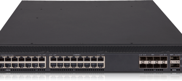
HPE 5700 48G physical configuration
The 5700 48G (model JG894A) is a datacenter switch composed of the following :
• On the front panel :
◦ 48 x fixed 1GbE base-T ports,
◦ 4 x 10GbE SFP+ ports,
◦ 2 x 40GbE QSFP+ ports.
• On the back :
◦ 1 x 1GbE base-T port, for OOBM (Out of Band Management) purpose,
◦ 1 x console port.
Switching between view/config mode and saving the config
When you first log in, you are in a display mode, which means you can only display the current configuration but take no configuration action (The command prompt is a superior sign).
Typing the command « system-view » take you to the configuration mode and the command prompt become a hash.
hpswitch>system-view
hpswitch#
Saving the running config is done via the « save » command. You can save the running config to startup config with the following command :
hpswitch# save force
The « force » parameter will avoid you confirmation & file naming prompts.
Configuring remote out of band management
This part is composed of five sub-tasks :
1. configure the oobm interface IP,
2. define the default gateway,
3. create a local user with admin rights,
4. activate a remote protocol (preferably ssh),
5. configure the vty (Virtual Teletype).
1. Configure management interface’s IP
After entering system-view mode, you select the management interface then set IP address and network mask.
interface M-GigabitEthernet0/0/0
 ip address 192.168.1.1 24
2. Configure default route on the management interface
ip route-static 0.0.0.0 0 M-GigabitEthernet 0/0/0 192.168.1.254 permanent
3. Create a local user, grant “network-admin” rights and SSH connection
line vty 0 15
 authentication-mode scheme
 protocol inbound ssh
Some useful commands
Configure an uplink in trunk mode and allow all VLANs
Interface GigabitEthernet 1/0/48
 port link-type trunk
 port trunk permit vlan all
Create an SVI for a vlan
interface Vlan-interface <vlan-id>
 ip address 10.0.0.252 24
Split 40GbE interfaces into 4 x 10GbE
The 40GbE interfaces can be split into 4 x 10GbE interfaces. You will need a break-out cable and the switch will have to reload.
Select a 40GbE interface in system-view mode and enter this command :
using tengige
You can see the 10GbE interfaces after the switch have rebooted. The break-out interfaces numbers are appended after a colon – Think sub-interface.
[HPE-5700]display interface brief
…
XGE1/0/53:1          UP   10G(a)  F(a)   A    1
XGE1/0/53:2          UP   10G(a)  F(a)   A    1
XGE1/0/53:3          UP   10G(a)  F(a)   A    1
XGE1/0/53:4          UP   10G(a)  F(a)   A    1
XGE1/0/54:1          UP   10G(a)  F(a)   A    1
XGE1/0/54:2          UP   10G(a)  F(a)   A    1
XGE1/0/54:3          UP   10G(a)  F(a)   A    1
XGE1/0/54:4          UP   10G(a)  F(a)   A    1
Configure a native vlan on a trunk port
Native vlan is possible when the port is operating in hybrid mode (you will have to first put the port on access mode, then activate hybrid mode).
[HPE-5700-Ten-GigabitEthernet1/0/53:1]port link-type hybrid
Please set the link type of the port to access first.
[HPE-5700-Ten-GigabitEthernet1/0/53:1]port link-type access
[HPE-5700-Ten-GigabitEthernet1/0/53:1]port link-type hybrid
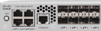
When you insert a GLC-T module without any previous configuration, you are likely to get the error ” SFP Validation Failed”, even if using a compatible module. This is because not all ports are capable to “downgrade” their functional speed to 1GbE : you have to insert the SFP in an eligible port and configure it. Best practice is to configure the port’s speed setting before inserting the SFP module.
GLC-T is the generic SKU for a Gigabit Ethernet SFP.
Set the port speed
conf
int e1/1
speed 1000
Insert the SFP in a 1/10GbE compatible port :
– for Nexus 5010 : ports 1 to 8,
– for Nexus 5020 : ports 1 to 16,
– for Nexus 5500/5600 : ports 1 to 32.
Note : On 5500/5600, when a port is configured with speed auto it will automatically select the right speed based on the inserted module.
Today I decided once again to stop fighting against apple’s devil plan to rule my wallet : I subscribed to an iCloud 200 GB storage plan.
I already have plenty of “databox”, either personal/free or corporate accounts, with free space. And to be honest, Apple’s databox is not the best one, nor the cheapest too. Yet I did the maths and came to the conclusion that for my particular use case, it’s a good enough solution with a fair price.
It’s a major mind shift for me : I always considered cloud databoxes overpriced.
My use case is pretty simple : I want to backup my iPhone, which hold up to 128 GB of data. Here is my context :
My main computer is a MacBook Air,
256 GB SSD, I value every single GB of it worthy to be traded on the comex market,
Anyway, my phone is plugged on the Mac approximately every ~never,
My central “home Mac mini” holding the “global” iTunes DB is left for dead for years now : so yesterday solution design,
I don’t want to feel the pain of managing (and carrying) USB drives & creating symlinks on my airbook to divert iPhone’s backup to it anymore : I value my time too much for that.
So I decided to be a nice cloud consumer, and delegate the hassle of running/maintaining the storage infrastructure : there is zero value doing it myself (geeky time is too precious to manage a backup nas@home).
Apple charge me 2.99€/month for 200 GB : that’s 35,88€/year.
200 GB is enough to hold all the data of my oneday-potentially full iphone (which is not atm), and leave me plenty of room for files on iCloud Drive and other “maybe one day” interesting services (iCloud photo library).
For the security & personal information aspect, I am willing to trust the cryptographic science (call me foolish).
A 200GB HDD is around 25€ on Amazon, so iCloud storage subscription is ~30% more expensive than a naked disk.
I consider this premium, as the price of peace of mind :
No need to provision space on the home nas,
Don’t need to run that disk 24/7 and care about HDD failure,
Nothing to do when I come home : it’s just backed up, no matter where I was the whole day/week.
Okay, an HDD you own is a onetime purchase, while Apple’s service is a subscription : I pay the HDD again every year.
So basically, it could be like I throw my 200GB HDD through the window each year and buy a new one : it make no economical or ecological sense.
But in fact it’s a greener option! The cloud storage have already been bought by someone else anyway : I am just using it. That drive space is absolutely more efficient than the one in my nas sitting on the living room : deduped/compressed for sure.
And finally, I can cancel my subscription anytime if I am considering that I can go without that iphone backup for a period.
The L1 & L2 links are dedicated physical ports (GbE) on UCS Fabric Interconnect platform, responsible of carrying the heartbeat traffic for the UCSM cluster. To be clear, both links are crucial to the survival of the cluster!
For the record, the Fabric Interconnects (or FI), are based on a Nexus hardware platform, tweaked for the job :
FI Gen 1 (6100XP) are based on Nexus 5000 physical platforms,
FI Gen 2 (6200UP) are based on Nexus 5500 physical platforms.
If you are wondering “What are theses L1 & L2 things for, on my brand new and shiny Nexus?”, here is the answer : nothing (on a Nexus). They are here from day one on Nexus, because it was planned from the start to decline the same hardware base and reuse it for Fabric Interconnects.
It’s just about rationalization of the production line : it’s cheaper to let the 4 GbE ports on all cases than handling several products.
Yes, the company that produced the Nexus line of product (Nuova Systems, acquired by Cisco on 2008) had UCS on mind from the beginning. If you look closer at the résumé of the co-founders of Nuova, all pieces comes together. They are the three musketeers as I tend to call them (even if “band” is mainly from Italy) : Mario Mazzola, Prem Jaim & Luca Cafiero. It’s not their first shot at creating a startup. But I will keep this story for another day – for another blog post, why not.
Talking back about L1 & L2 ports, if we keep on the analogy to the Nexus platform, we can say that L1 & L2 could play the same role of VPC Peer-Links on a VPC, minus some details. Explained that way, I am sure it is more clear for everybody 🙂
Note : L1 & L2 ports connection are done this way :
FI-A L1 <-> FI-B L1,
FI-A L2 <-> FI-B L2.
Key point, no switch between L1 & L2!!! They are channel bonded, and expect another Fabric Interconnect at the other edge. Don’t try to workaround, and connect both Fabric Interconnects through a switch : this is explicitly not supported.
The heartbeat traffic
UCSM is the management software of the UCS platform. It’s embedded on each Fabric Interconnect and run in an Active/Stand-by way. The motivation and the revelence behind this choice, rather than opting for an installed of VM hosted application could feed an entire tribe of Trolls.
– We do love Trolls around here, but they will be fed another time on another blog post (again!) –
Like any clustered application, signaling link is required to keep up a good knowledge of each member’s health : it’s usually the role of a redundant heartbeat link, in other words a messaging bus.
So we are dealing here with a two member cluster, and it is not a detail.
Loosing a member and Split-Brain
The cluster use the heartbeat link to monitor the health status of each member, and failover the services on the healthy member when disaster occur. A member is deemed healthy, if a quorum can be reached among cluster members. When the cluster consist of only two members, it’s the word of one against the other … So we need a referee (called “Tie-Breaker”, “Failover Monitor” or “Witness” depending on the technology), in order to avoid split-brain. On a UCSM cluster, it’s the default gateway that play this referee job when one member can’t join the other.
Note : UCSM cluster do some other testing between FI and chassis. The FI check if the chassis’s SEEPROM is reachable. The following article on UCSGuru dive a bit more about the tests and the particular case of C-Series servers, which don’t have SEEPROM : HA with UCSM Integrated Rack Mounts.
What’s happening when L1&L2 link is down on a UCSM Cluster.
Ok, that was a pretty long introduction, to finally come the first question. What’s the observed behaviour from an operator/administrator point of view?
When one of the links become down, a “major” alert is raised on UCSM for each FI : “HA Cluster Interconnect Link Failure”.
Error “immediately” visible,
No impact on data path.
When both links are down (L1 & L2), after a timeout period (about minutes) :
A new error is raised, this one is “Critical” : “HA Cluster Interconnect Total link failure”,
Subordinate FI is deemed unreachable,
The B side is shut (assuming that B was the subordinate), DATA PATH included :
FEX,
LAN & SAN uplinks.
So keep an eye on your L1 & L2 links, and be sure that at least one of them is always up.
Unfortunately I don’t know the exact duration of the timeout. At least, I can say we are talking about minutes.
To keep comparing with Nexus and VPC, we can see a similar behaviour when VPC Peer-Link is down : the secondary is sacrificed on the split-brain altar.
Back to a nominal situation
As soon as at least one link is back alive :
Resync of subordinate FI on the primary,
Data links reactivation,
UCSM cluster back alive.
Some best practices about L1&L2
L1 & L2 links should be direct-connected, no switch between them,
During a migration or a physical move, it may happen to have only L1 active for a period of time, but keep it as short as possible and bring him back his L2 buddy as soon as possible,
It is about Ethernet : keep in mind distance limitations, don’t stretch more than 100 meters!
Update October 27th 2015 At the time writing this article, I mentioned my experience on upgrading from version 2.2(3a), and the unexpected reboots of “some” blades. It turns this bug have been identified and is fixed since 2.2(3g). I forgot to update this article as promised : thanks to Patrick for asking after in the comments. 🙂
First to narrow the scope, the problem affected only UCS B200 M4. It was not obvious for me, as it was a greenfield deployment with only B200 M4 blades. It’s logged under bug number CSCut61527.
What is it about? The B200 M4’s BMC (Baseboard Management Card, a part of IPMI/CIMC system) sometimes return an invalid FRU and make the blade reboot … Yeah you read it right : a management controller taking potentially down production workloads …
This caveat is around since 2.2(3a) and 2.2(1b), and was fixed first on release 2.2(3g). Here is the link to the proper section of Release Notes for UCSM 2.2. When you are there, just look for CSCut61527 at the 10th row in the table.
Lesson learned : always double-check your current UCSM version before adding B200 M4 blades if it’s not a greenfield deployment! —
There is plenty of writing about “how to upgrade UCS” (from official Cisco documentation to independent blog posts) but I found none going from UCSM up to ESXi drivers (disclaimer : I looked after it less than 5min :-).
So here is my 2 cents on the matter.
What do I need to update my UCS system?
The detailed list of objects you need to upgrade are the following, from top-to-bottom :
UCSM itself, which is a cluster management software running in Active/Passive mode on Fabric Interconnects,
The Fabric Interconnects,
The IO Modules, aka FEXs,
Servers (either Blade or Rack format), whichcan be separated in three major section :
BIOS,
Controllers (SAS, CIMC),
Adapters cards,
Drivers, specific to your Operating System.
This document is old and some information may be outdated, but still describe quite well the “What” : Cisco UCS Firmware Versioning.
Where should I look for the software pieces?
It is rare enough for Cisco products to be mentioned : you don’t need to have a system linked to your CCOID to be able to download UCS related software 🙂
Fortunately, all pieces of software listed on the previous section are grouped by bundles and you don’t have (anymore) to download each packages separately :
Infrastructure Bundle : it contains UCSM, FI and FEX softwares/firmwares,
B-Series or C-Series Bundle : it contains BIOS, Controllers and Adapter cards firmwares,
An ISO with all C-Series or B-Series drivers.
Note : Instead of downloading 2GB of drivers, if you are looking for drivers on a particular Operating System, it may be better to look for Cisco UCS drivers on the OS editor’s site. For example if you look for the lastest Cisco UCS enic and fnic drivers for VMware, you can find them on vmware.com. It’s a 2MB download versus 2GB …
Updating the UCS system
In this section, I will not go for a screen-by-screen explanation but will rather explain the key steps and possible warnings you need to be aware of before starting the upgrade.
First, the documentation you should definitely check :
At the time of writing this article, with the current version being 2.2(3e), the recommend upgrade path is Top-to-Bottom, it’s generally the way to go. Yet on some earlier versions (1.4 if I am correct), required Bottom-to-Top.
It’s really unlikely that would change back again, but you should definitely check the documentation and the last release note update to know what’s the current and supported method. Here is Upgrading Cisco UCS from Release 2.1 to Release 2.2 document.
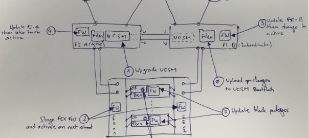
This doodle illustrate the updated parts and the actual order to follow.
Step 0 is about preparation. You need to upload the firmware packages to the Fabric Interconnect boot flash (the packages are copied to both fabric interconnects).
Upgrade the UCSM Software. It’s supposed to be non-disruptive for data path and you should only relaunch the UCSM client. My recent experience when upgrading from 2.2(3a) to 2.2(3d) was catastrophic : some blades rebooted randomly 4-5 times … Not so “non-disruptive”. I managed to reproduce the same behavior on another system and a SR is currently open. I may update this post later depending on the SR’s issue.
Stage the Firmware (~10-20min) on all FEXs (“Update Firmware” on Equipment>Firmware Management>Installed Firmware”) and set it to be active on next reboot (“Activate Firmware” without forgetting the related “active on next reboot” checkbox). This will save you a reboot, as the FEX will reboot anyway when the Fabric Interconnect will be upgraded,
Upgrade the Fabric Interconnect which is holding the secondary role, wait for reboot (~15min) then change the cluster lead to get primary on the newly updated FI,
Upgrade the remaining Fabric Interconnect and wait for reboot (~15min), then take back the cluster lead to the initial state (there is no automatic fail-back for UCSM),
Update the blades : best way is through Maintenance and Firmware Policies,
Be sure that your service profile is set to “User Ack” for maintenance Policy,
For ESXi node, take it in maintenance mode first from your vSphere Client,
Ack the reboot request on UCSM as your ESX nodes are in Maintenance mode.
Note : you can edit the default “Host Firmware Package” policy to use the right package version (for blade and rack), even without any service profile created. This way, any UCS server connected to the fabric will be automatically updated to the desired baseline. This will effectively prevent running different firmware due to different shipping/buying batches.
Most upgrade guides stop here, right after updating the hardware. Let me say that it’s golden path to #fail 🙂. The next part is about updating your ESXi driver to the most current driver version, supported by your UCS firmware release.
Updating VMware ESXi drivers
At the end of the day, what matter is how your Operating System handle your hardware. That is the driver’s job. If it’s obsolete, either it works non-optimized and without “new features/enhancements” (that’s the best option) or it may lead to some unpredictable behaviors …
Bets are high you installed your ESXi on a UCS server using a Custom ISO, available at vmware.com. Bets are higher that as the VIC card’s exposed vETH and vHBA are recognized, nobody has bothered to update them. If so, you run with a 2-3 years old driver …
You can check your current enic (vETH) and fnic (vHBA) driver version on your ESXi host with the following commands :
#vmkload_mod -s enic
#vmkload_mod -s fnic
If you find Enic version 2.12.42 and Fnic version 1.6.0.5, you run the ISO’s version and I would highly recommend to upgrade.
Download your drivers at vmware.com following this navigation path : vmware.com > download > vsphere > Driver & Tools.
Select the relevant vSphere version (5.X, do not choice “update 01, 02” links),
Download Drivers for Cisco enic and fnic.
It’s 1MB per download on vmware.com, compared to the UCS Drivers ISO on Cisco.com which contains all drivers for all systems, but worth 2GB …
To apply the update, you have choice between esxcli on the esx shell, or via Update Manager.
No rocket science here, just follow this standard VMware KB and pick an option you are comfortable with : http://kb.vmware.com/kb/2005205 or KB1032936 for vSphere 4.x.
Reminder : you do NOT need a Windows based vCenter when using Update Manager. You just have to plan a Windows system to install VMware Update Manager utility, then you can enjoy using vCenter Appliance.
In addition, this Troubleshooting Technote go into all the details regarding how to check and update UCS Drivers for ESXi, Windows Server and Linux (Red Hat & Suse).
No, I am not going to talk about Call of Duty. At least not today, not on this blog post, even maybe not during this life … 🙂
So what’s CoD and what the hell this have to do with VMware? CoD stands for Cluster-on-Die, a new NUMA setting found on some shiny Intel Haswell processors, aka E5-v3.
It’s active by default.
Side note on this Feature With Haswell, Intel have gone wild and each processor can hold up to 18 cores! That’s a lot, but nothing new here. The bottom line is that with so many cores on a single socket, it may lead to more latency toward memory access with some workloads.
So there is a bunch of new features, to get you confused have choice and find the best suiting option for your context.
Here is a link to a Cisco white paper, talking about the UCS B200 M4 and BIOS tuning for performance. You could find there plenty of details on each new BIOS settings. The following is an abstract for the “Cluster on Die Snoop” functionality
Cluster on Die Snoop Cluster on Die (CoD) snoop is available on Intel Xeon processor E5-2600 v3 CPUs that have 10 or more cores. Note that some software packages do not support this setting: for example, at the time of writing, VMware vSphere does not support this setting. CoD snoop is the best setting to use when NUMA is enabled and the system is running a well-behaved NUMA application. A well-behaved NUMA application is one that generally accesses only memory attached to the local CPU. CoD snoop provides the best overall latency and bandwidth performance for memory access to the local CPU. For access to remote CPUs, however, this setting results in higher latency and lower bandwidth. This snoop mode is not advised when NUMA is disabled.
Problem : VMware doesn’t support this new option. It’s outlined on the KB2087032, for vSphere 5.1 in the front line, but you can read that this problem persist for vSphere 5.5.
I ran on this problem with a brand new UCS M4, the result (that I am aware of) is pretty fun : vSphere host see 4 sockets instead of 2 sockets … Licensing guys @VMware will be happy 🙂
Workaround : This is a well-known issue today for vSphere, and no doubt it will be fixed soon by VMware. In the mean time, the recommended action is to “disable” this setting. Actually, you cannot “disable” it, you just have to choose another CPU snoop mode. The best balanced mode seems to be “Home Snoop” mode.
Home Snoop Home Snoop (HS) is also available on all Intel Xeon processor E5-2600 v3 CPUs and is excellent for NUMA applications that need to reach a remote CPU on a regular basis. Of the snoop modes, HS provides the best remote CPU bandwidth and latency, but with the penalty of slightly higher local latency, and is the best choice for memory and bandwidth-intensive applications: such as, certain decision support system (DSS) database workloads.
The Third available mode for CPU Snooping defined by Intel on E5-2600 v3 is “Early Snoop”, which is best suited for low latency environments.
Changing the BIOS policy for this value take effect immediately, without needing to reboot. vSphere see that change immediately and report the correct socket number.


Recent Comments